Updated July 7, 2023

Introduction to 3D Gaming Models
3d Gaming models are the three dimensional designed model of particular characters which is used in 3d game animation. Nowadays, we have many different types of 3d gaming models software. Autodesk Maya software and 3ds Max software are one of them. You can use any one of them as a beginner in 3d game modeling.
In 3d modeling, we use different types of commands, geometrical data, and tools for making a wireframe of particular characters and assets of the game. For becoming a game developer, you just have a creative mind and learning capability of different ideas.
Steps for Creating 3D Game Model
Here I will show you 3d game modeling in one of the 3d modeling software, and for 3d game modeling, I will use 3ds max here. You can use any 3d designing software available in the market. I will generate a character model here as an example of our 3d game model. So let’s start our tutorial for 3d character modeling.
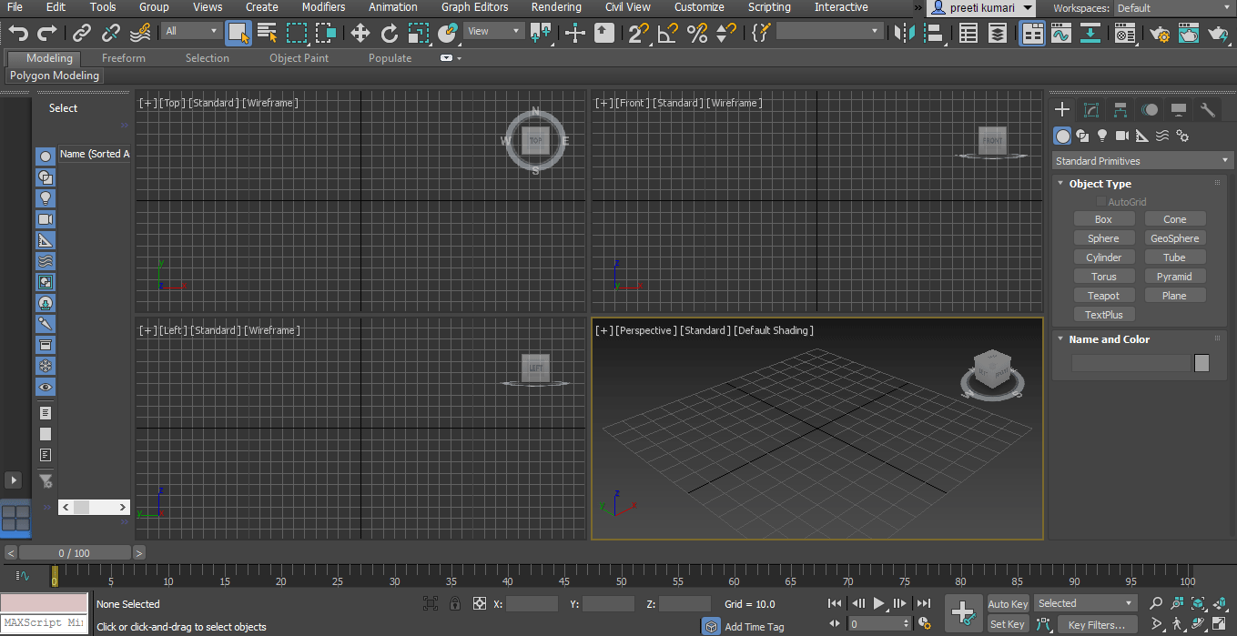
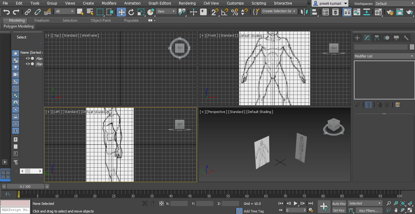
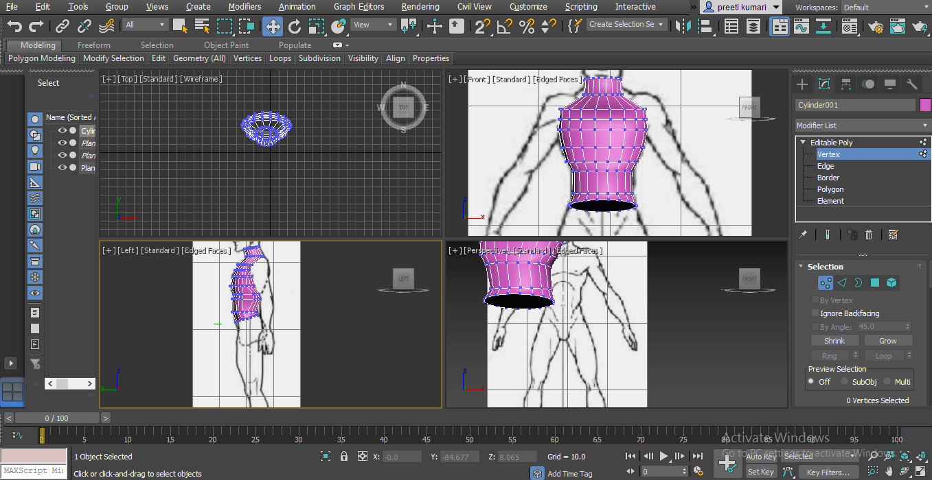
This is the User Interface of 3ds max software. In its working area, we have a different section for having ease in our work. The section is a Common panel section at the right-hand side, Timeline section for animation at the button, Tool panel at the top of the work area, Viewport for working, etc. We have four viewports here Top Viewport, Front viewport, side viewport and Perspective viewport for all direction view. Let’s look at the steps to create.
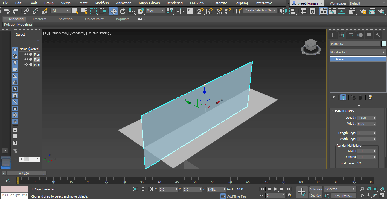
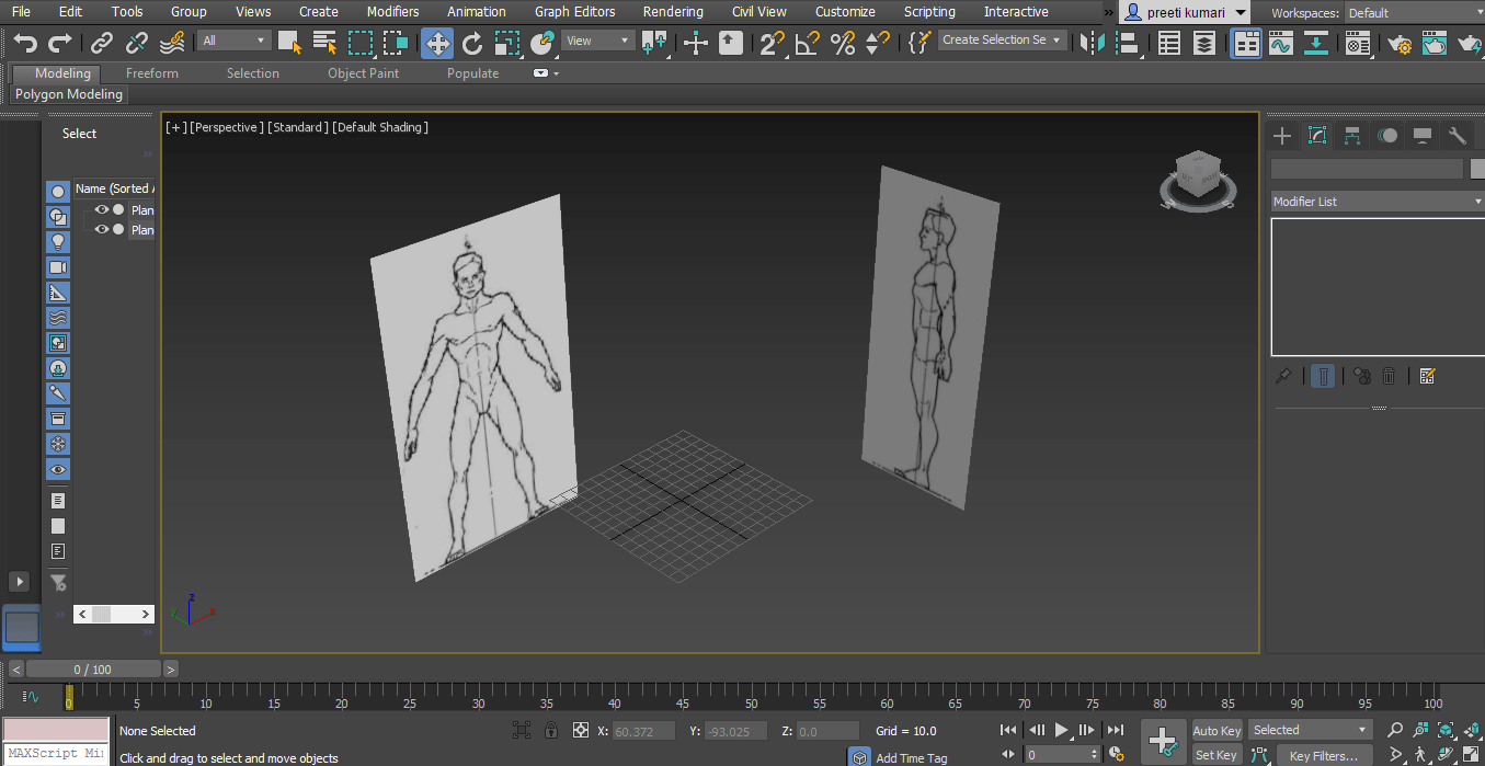
Step 1: First of all, we take a blueprint for 3d character. You can download it from the internet. Now take two planes of the same size according to our character blueprint for the blueprint’s front and side view.
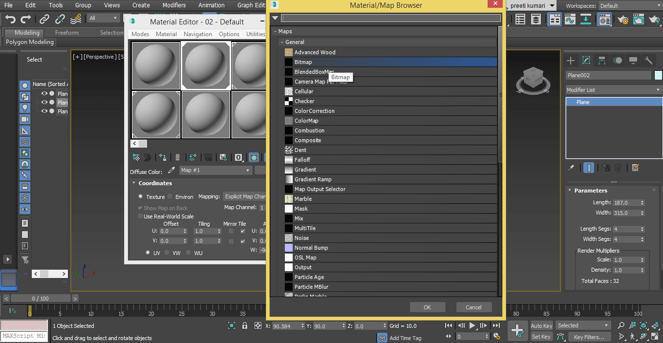
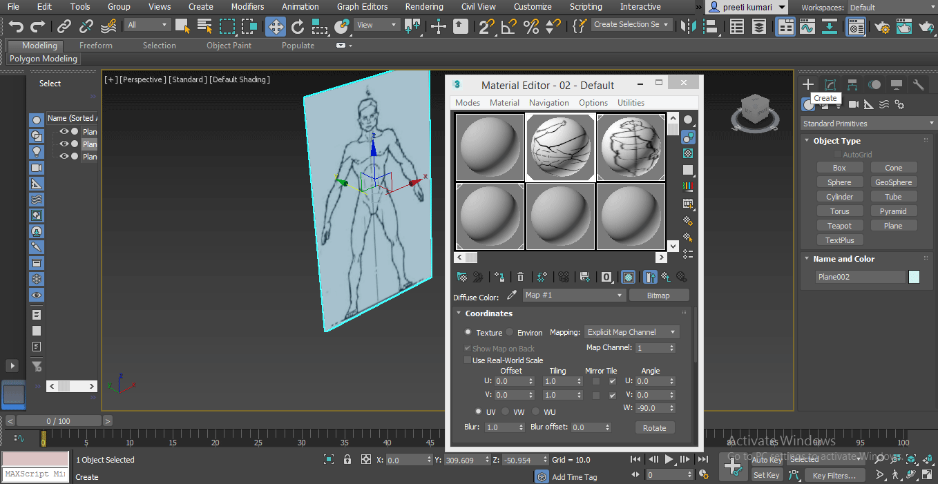
Step 2: Now, we will assign blueprints to these planes. Press M on the keyboard to open the Martial Editor box and assign marital to these planes.
A dialog box will open. Click on the diffuse color option of this box. Again a dialog box of Material will be open. Choose a bitmap from this dialog box and press on the OK tab of this box.
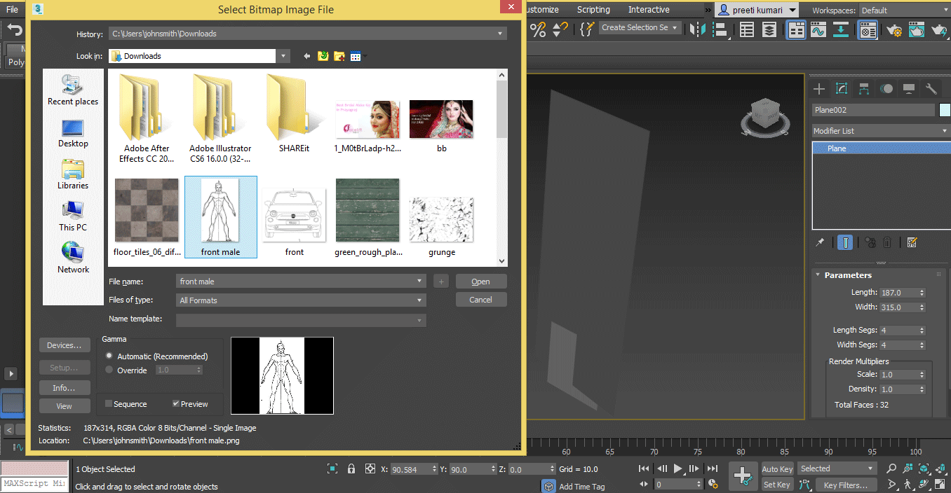
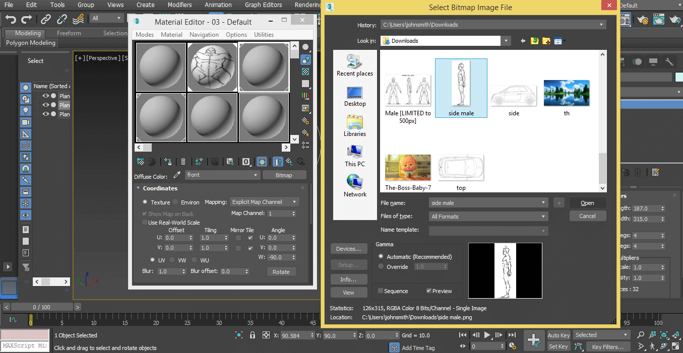
Step 3: A dialog box will open. Go to the location where you saved your blueprint. I will choose the front view here. Press the open tab button to assign this as material and name it as a front view.
Step 4: Again, follow the same steps to assign a side view as material and name it as a side view.
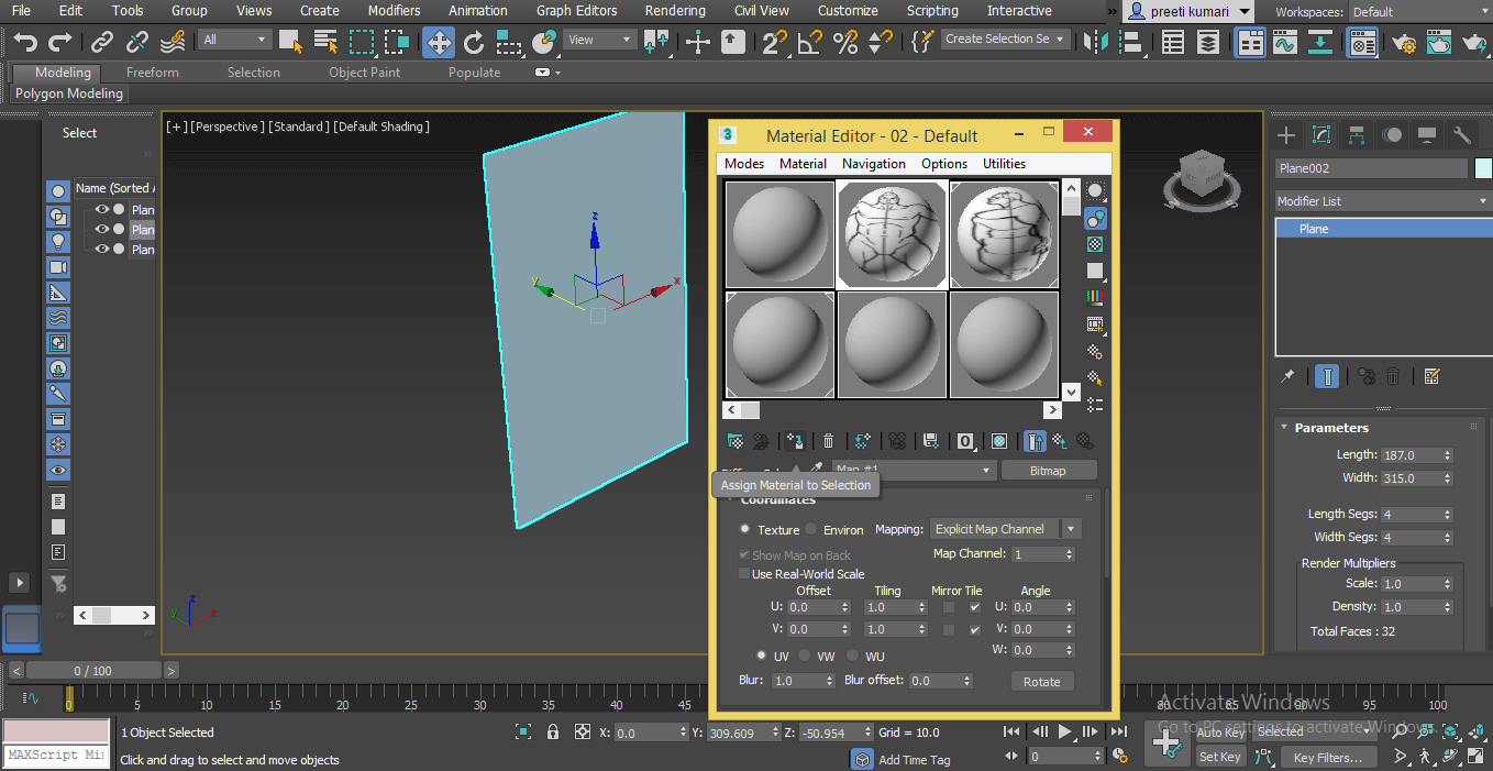
Step 5: Now select the front plane and click on the button ‘Assign Material to selection’ to assign material to the front plane.
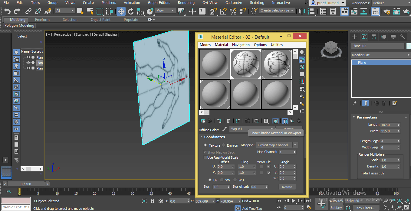
Step 6: And then click on the ‘Show Shaded Material in viewport’ button to see this material on the front plane.
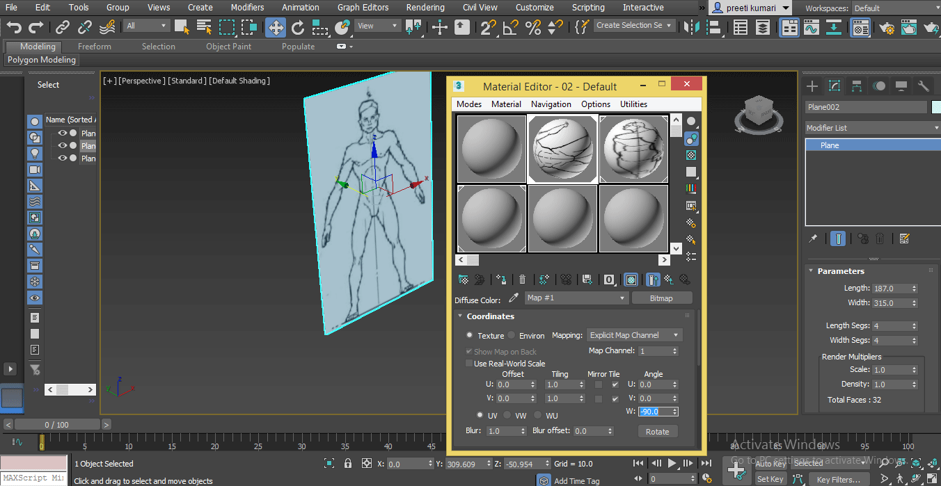
If the blueprint is not in the right direction, change the direction by changing the value of the angle in the W direction option.
Follow the same steps for the side view plane and assign a side view blueprint inside the view plane.
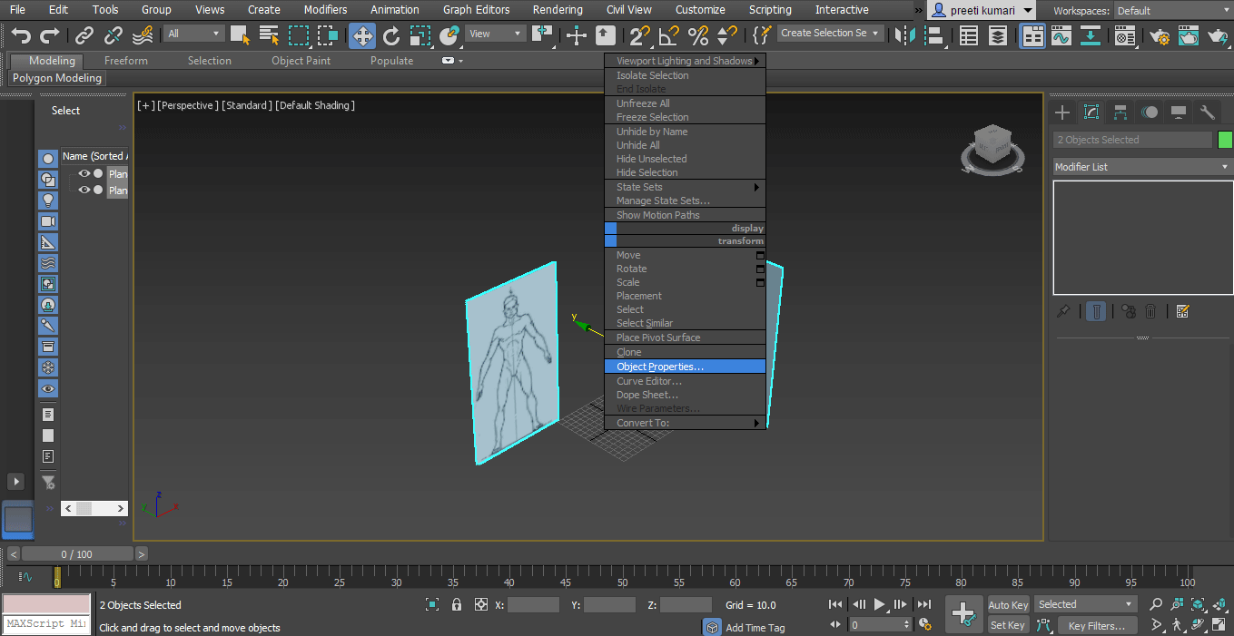
Step 7: Now, we will freeze these planes so that they will not create any problem during modeling. For freezing plane selects both the plane. Click right on the mouse button; a drop-down list will open. Choose ‘Object property option’ here.
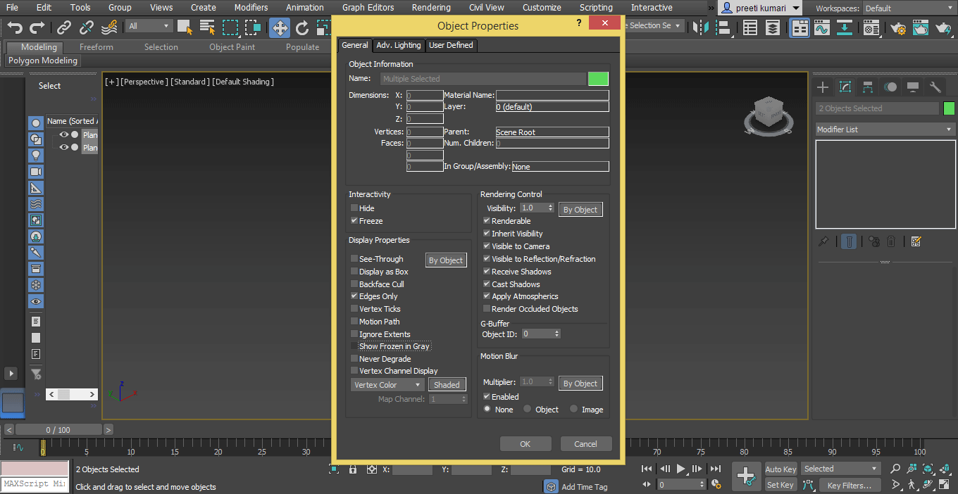
Step 8: A dialog box of Object Properties will open. Check tick mark On of Freeze option and uncheck ‘Show frozen in Gray’ option of this dialog box. Press ok from the ok tab button of this dialog box to freeze the planes.
Step 9: Now, we will go to the front viewport and press F3 on the keyboard to see our front blueprint in front view, and then we will go to the side viewport and again press F3 on the keyboard to see the side blueprint here.
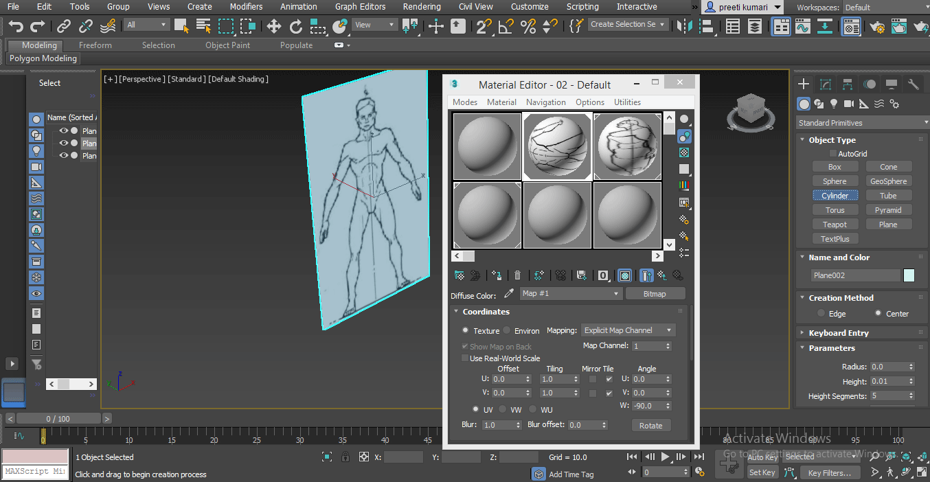
Step 10: Now go to create a tab of the common panel.
Choose the Cylinder command from here by clicking on a common panel’s Cylinder tab button to activate the cylinder command.
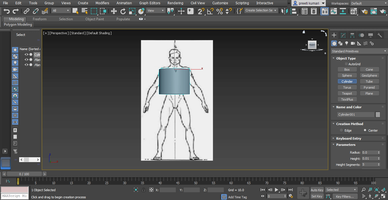
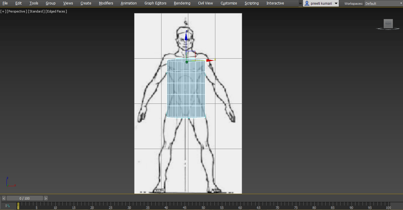
Step 11: Now, we will draw a cylinder according to our body shape.
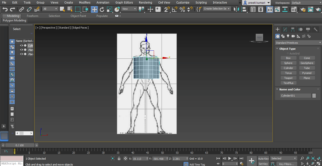
To see the line segment in the cylinder. Press F4 on the keyboard.
Step 12: Press the Alt+X keys on the keyboard to see through the cylinder so that we can easily trace the blueprint. See-through means make any object transparent.
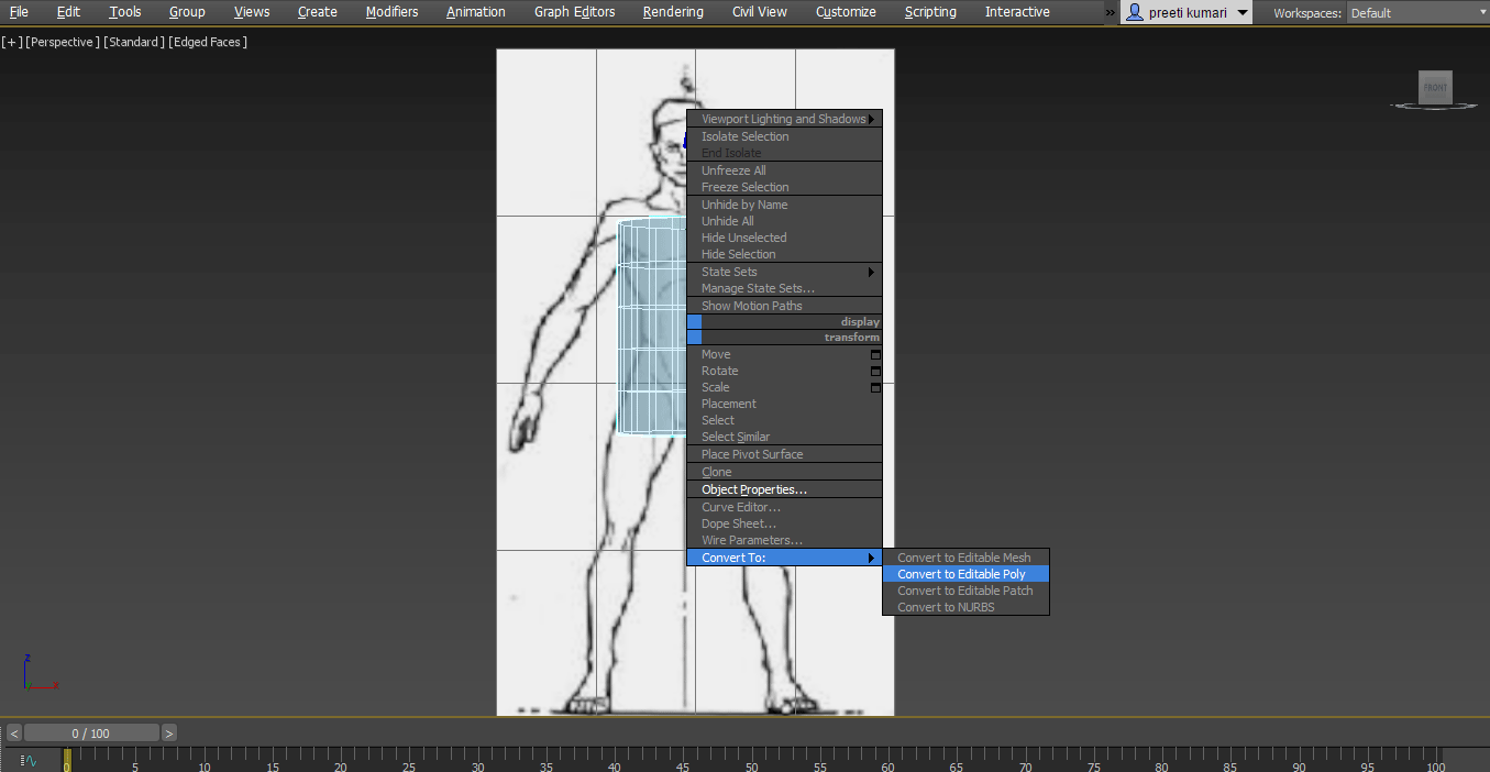
Step 13: Now, we will convert it to poly. To convert it into poly, right-click on the mouse. Go to the ‘Convert to’ option. Choose the ‘Convert to Editable Poly’ option here. You can also use the Editable Mesh option or Editable Patch option, or NURBS for this work, but the Editable Poly option is best for this work.
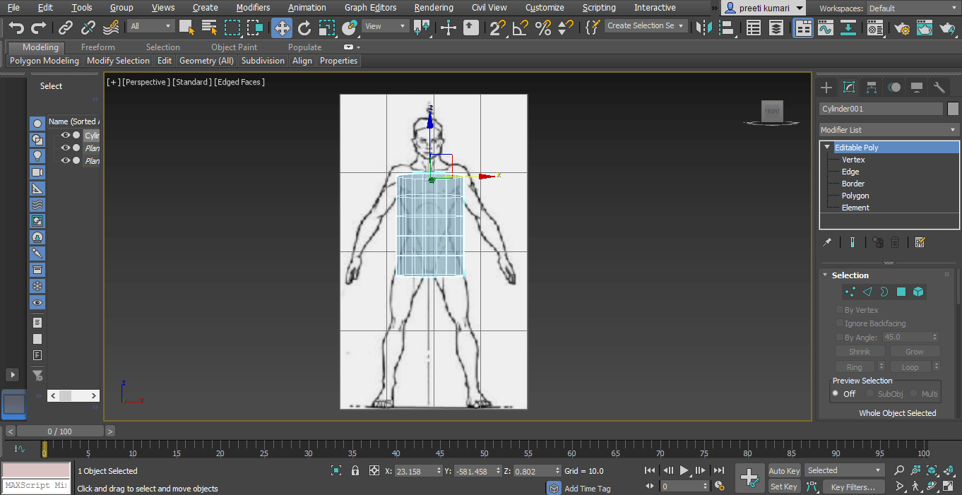
We have different parameters here in Editable Poly to edit the wireframe of the cylinder according to our blueprint: Vertex, Edge, Border, Polygon, and Element.
Step 14: Now, we will adjust the cylinder according to our blueprint by using the rotate command, move command and scale commands, which are present at the top of the working area.
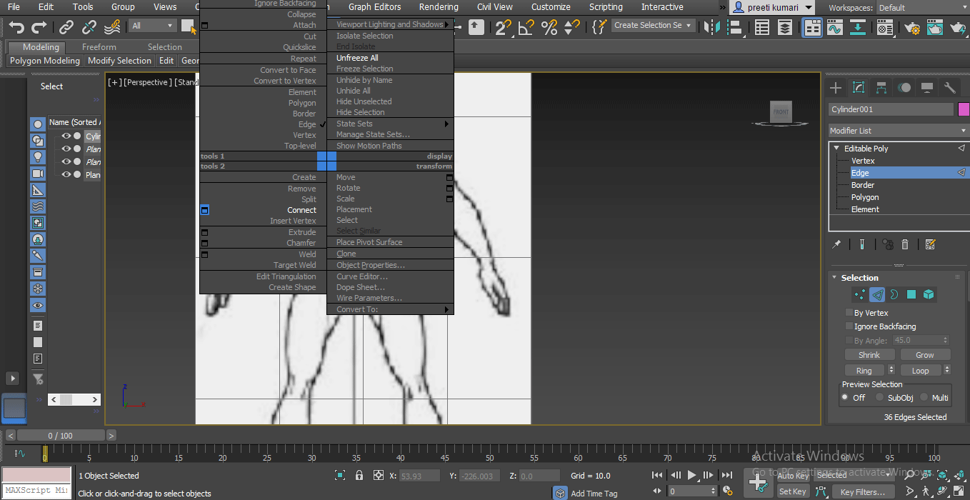
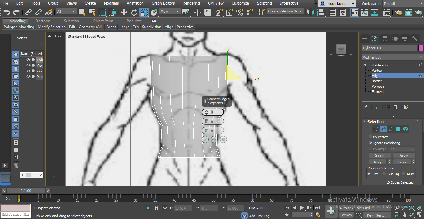
Step 15: Now, for an increasing segment in-cylinder, choose Edge from Editable poly parameter options. Then select the part in which you want to increase segment and right-click on the work area. A drop-down list will open. Go to the Connect option. Click on the small window icon of the Connect option.
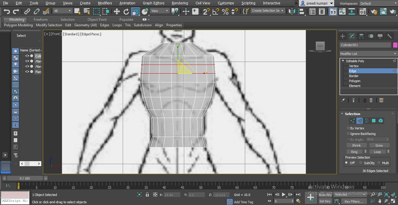
Some tab will be an option on the working screen. Now give segment according to your requirement here.
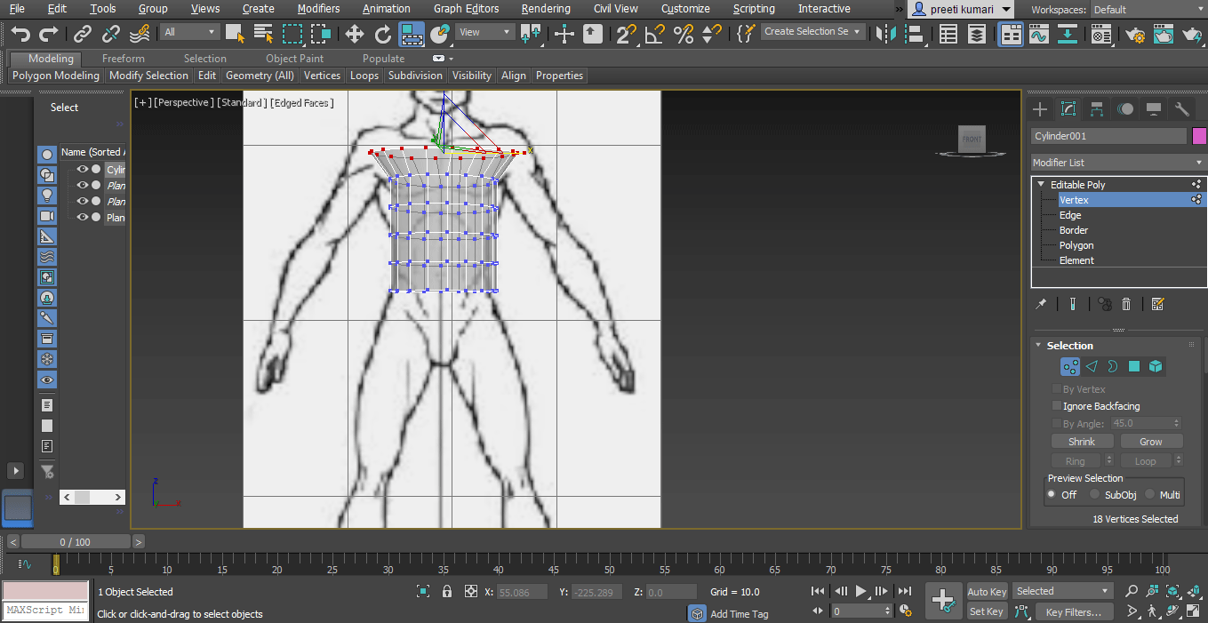
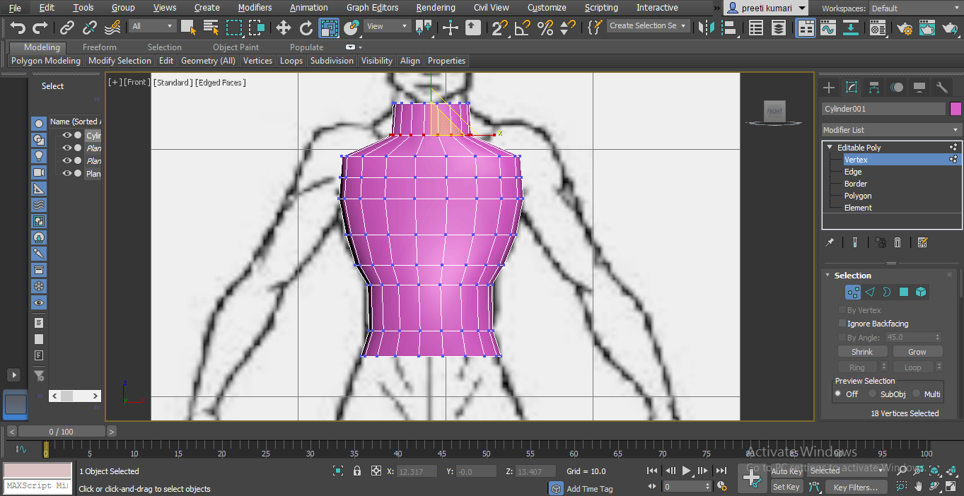
Step 16: And move upper vertex points in the upper direction for making the neck area.
You can give a segment on any plane at any time.
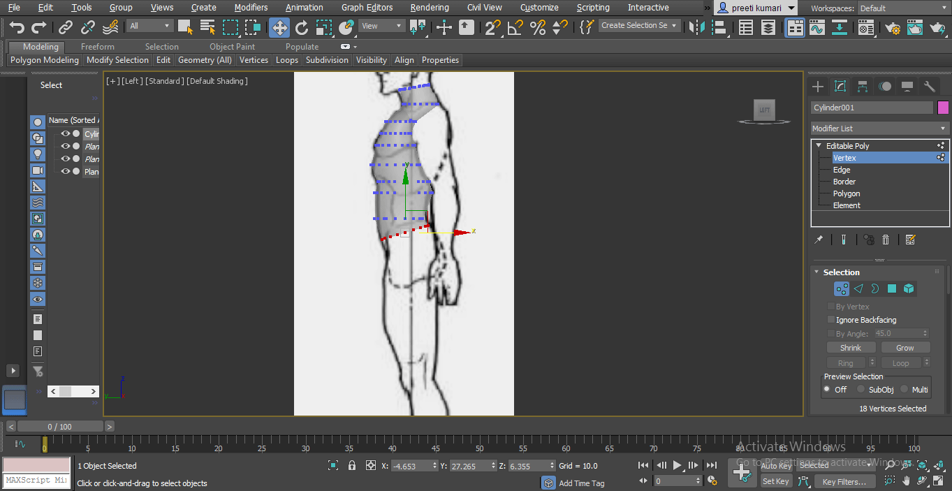
Step 17: At the same time, go to the side viewport and set the Change the Cylinder Shape from here according to the blueprint.
By following the same steps and using the edit command, you can easily make all part of your model.
This is the way by which you can make models in 3d designing software. Here I have just shown you one software you can learn in other software too.
Conclusion
After this training, you can find a big change in your knowledge of 3d game modeling. 3d Game model adds a plus point in your career-building steps, and you can develop your interest in 3d models in a more effective way after having a look at our 3d model examples of this article.
Recommended Articles
This is a guide to 3D Gaming Models. Here we discuss the Introduction to 3D Gaming Models along with steps for creating a model in 3d game. You may also look at the following articles to learn more –
