Introduction to AutoCAD PressPull
AutoCad is a 2d and 3d computer-aided designing software which has a number of commands for making its work easy for its users. You will learn many commands in this software throughout your learning. Today we will discuss one of them that is the PressPull command. This is a part of modeling command of this software which is a combination of extruding and subtract command of AutoCad software. By the PressPull command, you can extrude any section of any model in a particular direction, or you can subtract any section of that model in a particular direction by using some simple steps. Here in this article, we will discuss this command and analyze the parameters of this command for having good knowledge about this command. So let us start our discussion about this topic.
How to Use PressPull in AutoCAD?
We can learn this command in a very simple manner without any problem because it is very similar to extrude and subtract command of AutoCad Software but before start learning about this command and its parameters, let us have a look at the working screen of this software so that we can better understand this topic throughout this article is a very interesting manner.
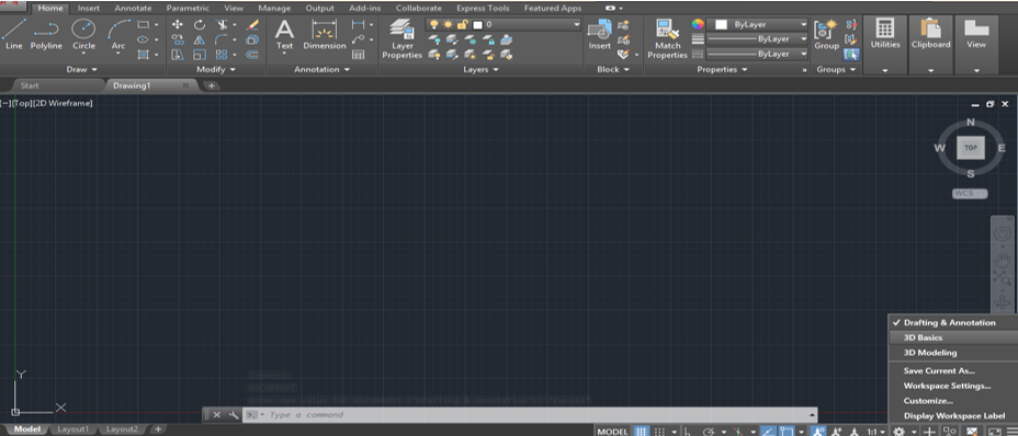
At the top of the working screen of this software, we have a ribbon which has a different type of tabs in it that are Home tab, Insert tab, Annotation tab, and many others which helps us in managing of their commands and, below this, we have a working window of this software in which we can see our current drawing, this working window has a navigation cube and options for changing the view of our drawing such as top view, side view, front view, and many other 3d views, below this working window we have some navigation option for handling our work during drawing.
Step 1: Your working window is set on the ‘Drafting & Annotation’ workspace screen by default. So for the Presspull command, we have to change it to modeling workspace screen. For changing it to modeling workspace screen, just click on the Workspace switcher option of this software which is at the navigation options, and click on the 3D Basics option.
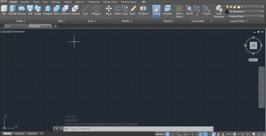
Step 2: Once you click on this option, your workspace will change to 3d Basics workspace, and your 3D Basics workspace will look like this.
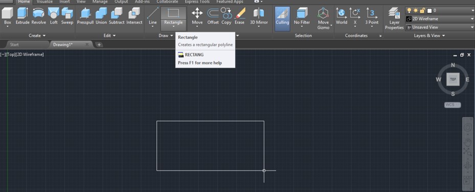
Step 3: Now, let us take a rectangle command from the Draw menu of the Home tab of this software which is at the top of the working window and draw a rectangle like this. You can draw a rectangle of any particular size by entering the values of it. I will draw a freehand rectangle then press the ESC button of the keyboard for exiting from the command.
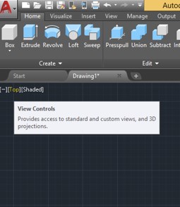
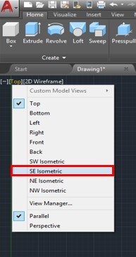
Step 4: Now come to the View control option of the working window, which is at the top of the working screen on the left side, then click on it for changing our view to southeast isometric view.
Step 5: Now, a drop-down list will be open once you click on the View control option. Choose the SE Isometric view option from the list for drawing 3d model.
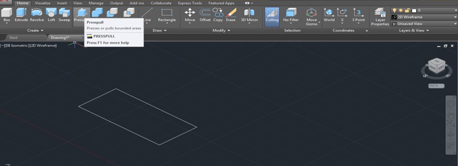
Step 6: Now, your rectangle will look like this when you change the view of your drawing. Now go to the ‘Create’ menu of the Home tab of this software and click on the icon of Presspull command for having it.
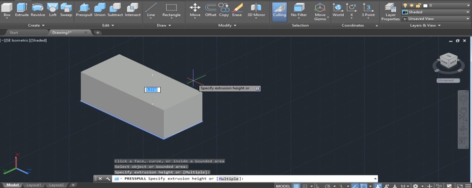
Step 7: Then, it will ask you to select the object. You can click inside the object or click on any side of the object for selecting this object for this command.
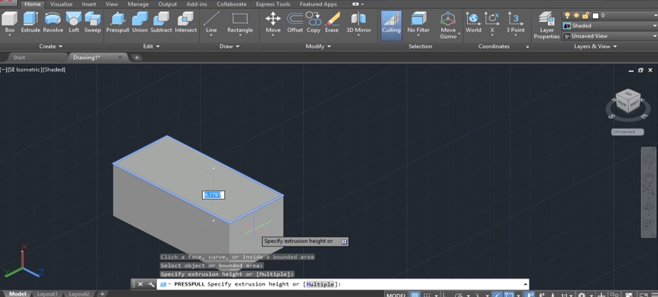
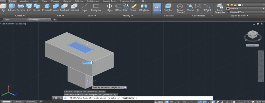
Step 8: Once you click on it, PressPull command covert this shape into 3d. Now you can extrude this shape in an upward direction or downward direction according to your requirement. For upward direction, drag the mouse cursor in an upward direction throughout this rectangle and make a click for applying extrude in this direction.
Step 9: For downward direction, drag the mouse cursor in down draw direction throughout this rectangle and make a click for applying extrusion in this direction.
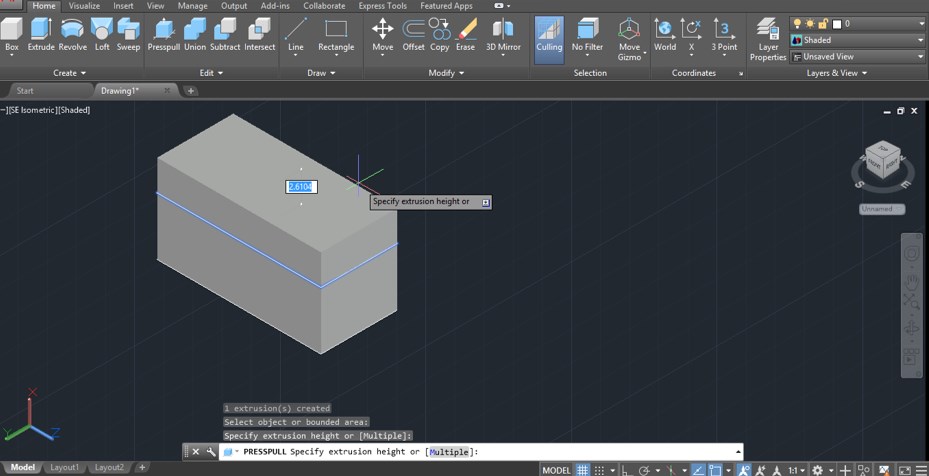
Step 10: Once you extrude this shape in the block, then you are free to extrude again and again with command. Just select any surface of this block again which you want to extrude by click on it then drag in your desired direction.
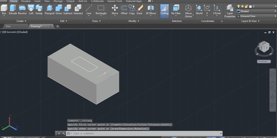
Step 11: Now, let us analyze how to substrate a shape from the 3d model with the help of the presspull command of this software. Again take the rectangle command from the Draw menu of the Home tab of this software by click on the icon of this command and draw a rectangle like this inside this block of any size.
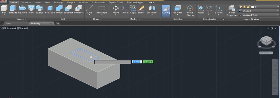
Step 12: Now again, take the Presspull command from the Create menu of the Home tab of this software by clicking on the icon of this command and selecting this small rectangle by clicking on the side of this command make click with the mouse button.
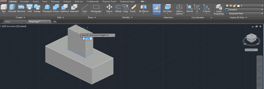
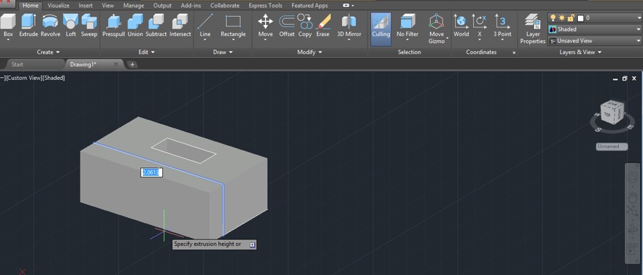
Step 13: Once you make a click command, it will coverts this rectangle into 3d block; then, you can drag it in the upward direction for extruding it like this.
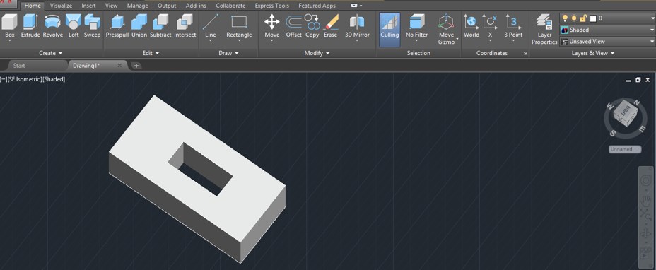
Step 14: But if you drag this 3d rectangle model in a downward direction throughout the block, the command will subtract this software.
Step 15: And subtracts this small rectangle from the block like this. You can check it by using the orbit command for rotating this model.
Step 16: Now again, you are free to extrude any face of this subtracted block with the help of the Presspull command. Just select that face of this block you want to extrude with this command and drag it in that direction you want to extrude that face.
In this way, you can use the PressPull command of Create menu of Home tab in AutoCad and use it for making models of drawing in your project work.
Conclusion
After going through this article, you can understand ‘what is PressPull command in AutoCad software and ‘how you can use it to make good drawing models in less time. You can practice these types of commands of AutoCad software so that you can enhance your designing skill for AutoCad software.
Recommended Articles
This is a guide to AutoCAD Presspull. Here we discuss an Introduction, how to use AutoCAD Presspull in a step by step manner. You can also go through our other related articles to learn more –

