Updated July 5, 2023

Introduction to Address Resolution Protocol
Address Resolution Protocol is an address mapping technique used to dynamically map a logical address to a physical address, i.e., convert the logical address (IP address) used at the network layer to physical address (MAC address) used at the data link layer. Package of Address Resolution protocol consists of a cache table, queues, output module, input module, and cache control module. In addition, address Resolution protocol consists of hardware type, protocol type, hardware length, protocol length, operations like request and reply, the sender’s hardware address, protocol address of the sender, the hardware address of target, and protocol address of the target.
Address Resolution Protocol Packet Format
Below tables is the ARP packet format:
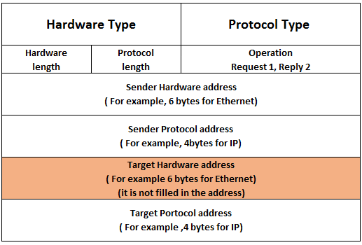
ARP Packet Format:
- Hardware type: It is a 16-bit field that defines the type of network on which address resolution protocol is running.
- Protocol type: It is a 16-bit field that defines the type of protocol. E.g., for the IPv4 protocol, this field contains 0800 bases 16.
- Hardware length: It is an 8-bit field that defines the physical address length in bytes.
- Protocol length: It is an 8-bit field that defines the logical address length in bytes.
- Operations: It is a 16-bit field that defines the types of packets. There are two types of packets ARP request (1) and ARP reply (2).
- Sender hardware address: It is a variable-length field that defines the physical address of the sender.
- Sender protocol address: It is a variable-length field that defines the logical address of the sender.
- Target hardware address: It is a variable-length field that defines the physical address of the receiver.
- Target protocol address: It is a variable-length field that defines the logical address of the receiver.
Address Resolution Protocol Operations
This section will see the ARP process and four different cases where the host or router needs to use address resolution protocol.

ARP Process:
Below is a list of steps involved in the ARP process:
Step 1: The sender knows the IP address of the receiver.
Step 2: The Internet protocol asks ARP to create an ARP request message that contains information like sender physical address, receiver physical address field is filled with 0s, the sender IP address and receiver IP address.
Step 3: ARP request message is sent to the data link layer where the message is encapsulated in the frame using the sender’s physical address as a source address and broadcast address as a destination address.
Step 4: Each and every host receives the frame because the frame contains a broadcast destination address. All hosts check the address with their address. If the match founds, the packet is dropped to that host; otherwise, it passes to the address resolution protocol.
Step 5: After receiving the packet target host reply with an ARP reply message that contains the target physical address. The message in this step is unicast.
Step 6: When the sender receives a reply message from the target, it knows the target’s physical address.
Step 7: Now, the IP Datagram carries data for the target machine encapsulated and sent in the unicast form to the destination.
Four Different Cases:
Below is the list of four cases where address resolution protocol services can be used.
Case 1:
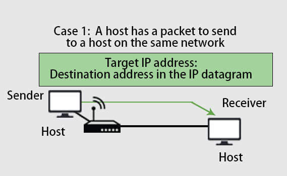
From the above picture, we can see that the sender is a host and wants to send a packet to another host that lies on the same network. In this case, mapping the logical address to the physical address is a destination IP address should be in the datagram header.
Case 2:
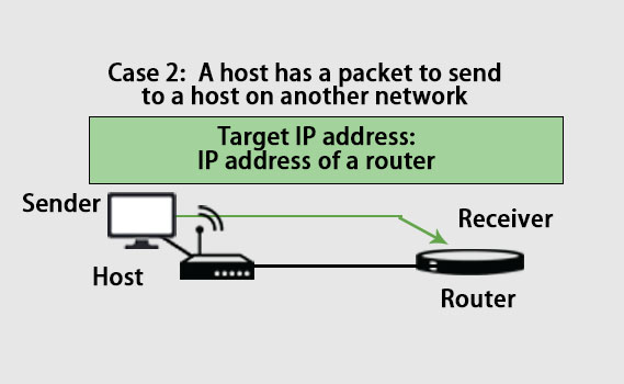
As we can see in the above picture, the sender is a host and wants to send a packet to another host that lies on another network. In this case, the sender host looks into the routing table to find the next host’s IP address for the destination. Thus, the host’s IP address becomes the logical address that must be mapped to a physical address. If the sender host does not have a routing table, it looks at the default host’s IP address.
Case 3:
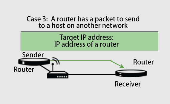
As we can see in the above picture, the sender is a router that received a datagram for another host that lies on another network. In this case, the router looks into the routing table and finds the next router’s IP address. Thus, the router’s IP address becomes the logical address that must be mapped to a physical address.
Case 4:
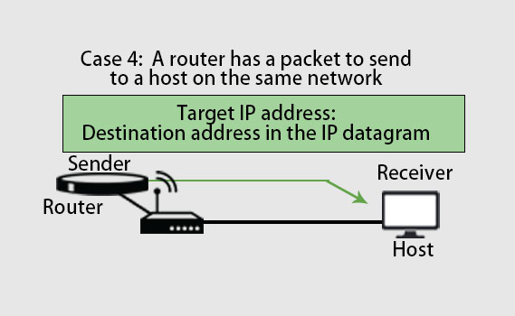
As we can see in the above picture, the sender is a router that received a datagram for another host that lies on the same network. In this case, the datagram’s IP address becomes the logical address that must be mapped to a physical address.
Address Resolution Protocol Package
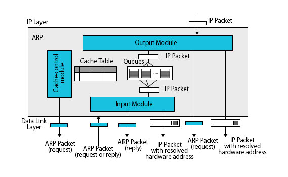
Address Resolution Protocol Package has five components:
- Cache table
- Queues
- Output module
- Input module
- Cache-control module
Below is the diagram of the address resolution protocol package:
1. Cache Table in ARP
When the host receives the IP datagram’s corresponding physical address, the Cache table saves this physical address in its table. Storing a physical address in the cache table is limited for a specific amount of time rather than unlimited time. The cache table is consists of an array of entries. Each entry has the following mentioned field.
- State: It shows the state of each entry. The state can be Free, Resolved or Pending. Free state means the time to live for entry has expired. That space is allocated to a new entry. Resolved state means the entry is completed. An entry has the destination physical address. Packages that are waiting to be sent to this destination can use the information in the entry. Pending state means the request for the entry has been stated and waiting for the reply.
- Hardware type: It defines the type of network on which the ARP package is running.
- Protocol type: It defines the type of protocol on which the ARP package is running.
- Hardware length: It defines the length of the physical address.
- Protocol length: It defines the length of the logical address.
- Hardware address: It shows the destination physical address.
- Protocol Address: It shows the destination logical address.
- Interface number: It is an interface number that the router uses to connect with a different network.
- Queue number: It uses queue number to enqueuer the packets that are waiting for address resolution.
- Time-out: It shows the lifetime of each entry in the second.
- Attempts: It shows the number of times the ARP request has been sent for each entry.
2. Queues
- It contains a set of queues for the destination, i.e. one queue for each destination to hold the IP package while it resolves the physical address.
- Finally, the output module sends unresolved packets to their corresponding queues.
3. Output Module
- The output model waits for IP packets. As soon as the IP packet receives, it checks the cache table to find the destination’s corresponding IP address present in the packet. The destination IP address of the packet must match the protocol address of the entry.
- If the matching entry founds and the state of the entry are RESOLVED, then the packet with the destination hardware address is passed to the data link layer for transmission.
- If the matching entry founds and the state of the entry are PENDING, then the packet waits until the destination’s hardware address is found.
- If the matching entry does not find, the output module creates a queue and enqueues the packet. Then, it creates a new entry and gives the state a PENDING and set attempts to 1. Finally, it broadcast the ARP request packet for the destination address.
4. Input Module
- Input Module waits for the address resolution protocol packet. As soon as the address resolution packet arrives, it checks the entry corresponding to the cash table’s address resolution packet. The protocol address of the target must match the protocol address of the entry.
- If the matching entry is found and the state of the entry is RESOLVED, the input module updates the entry and time outfield. Entry is updated because there can be chances of change in the hardware address.
- If the matching entry is found and the state of the entry is PENDING, the input module updates the entry by copying the target’s hardware address to the hardware address field of the entry and updating the state field to RESOLVED. It also updates the timeout field of the entry.
- If the matching entry is not found, the input module creates a new entry and adds it to the table. It updates the state field to RESOLVED and time outfield of the entry.
- Then the input module checks whether the ARP packet that is received is a reply or request. If it is an ARP request, the input module immediately creates an ARP reply and sends it to the sender. ARP reply packet is created by changing the value of the packet from request to reply.
5. Cache-Control Module
- The cache-control module maintains the cache table. It checks the cache table entry by entry periodically, i.e. five seconds.
- If the state field of the entry is FREE, it checks another entry.
- If the state field of the entry is PENDING, the cache-control module increases the attempt field’s value by 1. It then checks the value of the attempt field. If the attempt field’s value is greater than the maximum limit that is allowed, it updates the state field to FREE and destroys the corresponding queue.
- If the state field of the entry is RESOLVED, the cache-control module decreases the time outfield value by 1. It then checks the value of the time outfield. If the time outfield value is less than or equal to zero, it updates the state field of entry to FREE and destroys the corresponding queue.
Conclusion
This article has seen what address resolution protocol, packet format in ARP, is an operation with images and explanation in the sub-topics for better understanding.
Recommended Articles
This has been a guide to Address Resolution Protocol. Here we have discussed packet format, operations, as well as components of the ARP package. You can also go through our other suggested articles to learn more –


