Updated July 4, 2023
Introduction to ARP Packet Format
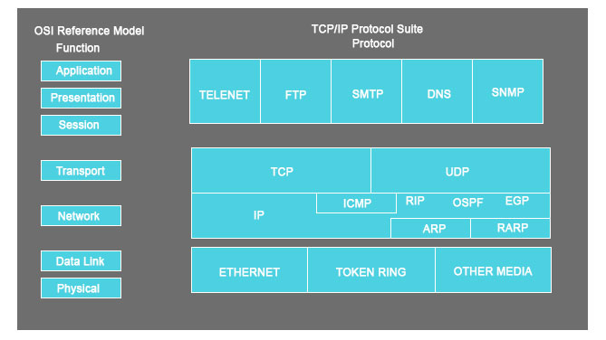
A hierarchal approach is a good practice, especially when you have to demonstrate something. So in this article, we will first cover the ‘Communication Protocol’ to understand how things work under ARP Packet Format and see what and how ARP constitutes the protocol suite.
Communication Protocol or Protocol suite is a rule that every entity of a communication system must follow when transmitting information using the physical medium. This protocol defines everything within it, like rules, syntax, semantics, and synchronization.
ARP, which stands for Address Resolution Protocol, is one of the many communication protocol components. The second thing is ARP works on the link-layer level. ARP helps in connecting the IP address to the physical machine address. For the IPV4 version, the commonly used I am 32 bits in length, whereas for an Ethernet local address, it is 48 bits long.
Why do we need ARP in the Communication Protocol?
“The real challenge lies in finding the IP packet addressing for MAC address; however, the source is easy to determine, but the destination is a tough task.”
So to determine the destination MAC address, there are several methods –
- Closed-form computation
- Table lookup
- Message Exchange
To all listed issues, ARP comes to the rescue; let us see how –
ARP is built into every node of the IP config, which means every system being developed on the IPV4 network has an ARP code.
In ARP, only two messages are defined – ARP request and ARP reply.
Now, we get back to the problem statement, which says, ‘The issue is there to find the destination MAC addressing.’
So, after a host finds out the destination’s MAC address, an ARP request is sent out. When this ARP request message is received, the destination will automatically send back an ARP reply.
What is happening here is that the ARP request asks, “Can I have the MAC address”? And the reply is, “Yes, you can.”
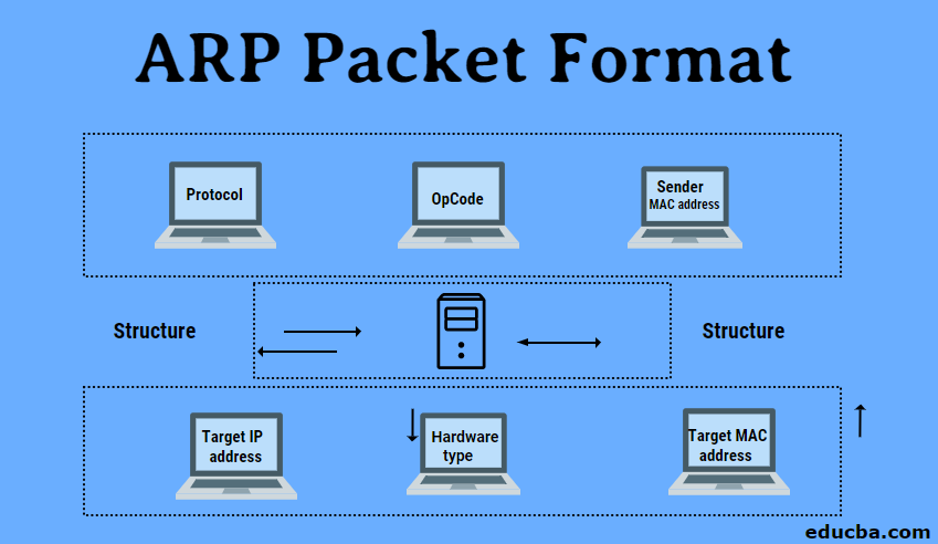
The Structure of Arp
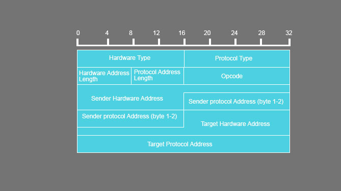
Below listed fields are there in an ARP message.
- Hardware Type: This is to specify the type of hardware used by the local network to transmit the Address Resolution Protocols message. Once common hardware under this category would be the ‘Ethernet’ with a value equal to 1, and the field size would be 2.
- Protocol Type: To assign a fixed number in this field, IPV4 has the number 2048.
- Hardware size: This is the length in bytes for the MAC address; generally, we see the ethernet has a MAC address of 6 bytes long.
- Protocol Size: It represents the length of the IPV4 logical address; the IPV4 address is generally 4 bytes long.
- OpCode: This is the length of the logical address in bytes; it specifies the nature of the ARP message. An ARP Request has an assigned value of 1, whereas the ARP reply holds the value of 2.
- Sender MAC address: Layer 2 address for the device sending the message.
- Sender IP address: Protocol address in IPV4 for the device sending the message.
- Target MAC address: Layer 2 of the intended receiver. This field holds no value during the request phase and works only during the reply phase.
- Target IP address: This address is the protocol address for the intended receiver.
Working of Arp Protocols
Two devices are there.
- Source device
- Destination device
So, these two want to communicate between them. The first thing to do in those processes would be for the source device to check its ARP cache and find out if it has a resolved MAC address for the destination device. If the MAC address is present in the resolved state, then it will utilize that MAC address to establish the communication.
But if the resolved ARP is not there, then the source machine will create the ARP request message and put its datalink address plus its IPv4 address as the sender protocols address. One thing to note is that here the ‘Target hardware address’ will be left blank as the machine tries to find out that the source also broadcasts the ARP message request to its local network.
After this, both devices compare the target protocol address with its protocol address. If there is no match, then it will be dropped then and there itself without any actions.
If the findings happen, an ARP message is generated. Here the targeted device takes the ‘Sender hardware Address’ and ‘Sender Protocol Address’ from the ARP message and uses these values for the targeted hardware and protocols.
Now the destination device will update its ARP cache as it needs to contact the sender machine to establish a connection. The source machine will process the ARP reply from its destination and store the ‘Sender hardware address.’
The last thing to perform before a successful connection is that the source machine will update its ARP cache with the sender hardware address and sender protocol address from the ARP reply message.
ARP Packet Diagram
Explain in Detail: Components of ARP Packet Format
| FIELD NAME | SIZE (BYTE) | DESCRIPTION | ||||||||||||||||||||
|
HRD |
2 |
Hardware type and value.
Ethernet = 1 IEEE 802 networks = 6 ARCNET = 6 Frame Relay = 15 Asynchronous Transfer Mode (ATM) = 16 HDLC = 17 Fibre Channel = 18 Asynchronous Transfer Mode (ATM) = 19 Serial Line = 20 |
||||||||||||||||||||
|
PRO |
2 |
this is a compliment for the Hardware type field, specifying the type of layer being used in the messages. For IPv4, the value is 2048, which also corresponds to the Ether code for the Internet Protocol. | ||||||||||||||||||||
| HLN | 1 | this is there to specify the length of the hardware-related addresses in the message. | ||||||||||||||||||||
| PLN | 1 | this determines how long the protocol address will be in the message. | ||||||||||||||||||||
|
OP |
2 |
This field demonstrates the nature of the ARP message. The first two values (i.e., 0 and 1) are used for regular ARP. Other values are being defined, have a look at the below-mentioned table –
|
||||||||||||||||||||
| SHA | Equal to the HLN field | Deals with the hardware address of the device that is sending the message | ||||||||||||||||||||
| SPA | Equal to the PLN field | The IP address of the device which is sending the message | ||||||||||||||||||||
| THA | Equals to HLN field | The hardware address of the device which is receiving the message | ||||||||||||||||||||
| TPA | Equals to PLN field | The IP address of the device is on the receiving end. |
Conclusion
Finally, we are at the concluding statement regarding the discussion e had in this article on ARP. We have seen the communication protocols structure (IPv4) and where ARP (the article’s title) lies in the communication protocol. We have also seen its role and how effectively it handles its responsibility while the communication is targeted. The ARP structure, the requirement for ARP, the ARP packet diagram, and its components have all been covered.
Recommended Articles
This is a guide to ARP Packet Format. Here we discuss the introduction to ARP Packet Format with its working structure and needs. You may also have a look at the following articles to learn more –


