Updated March 15, 2023

Introduction to UML Object Diagram
A UML object diagram signifies a particular instance of a class diagram during a specific instant. Once showed visually, you will see a large number of parallels towards the class diagram. Object diagrams prefer to render a collection of objects and their associations as an instance.
What is Object Diagram in UML?
An object diagram concentrates on the attributes of a collection of objects as well as how those objects align with each other.
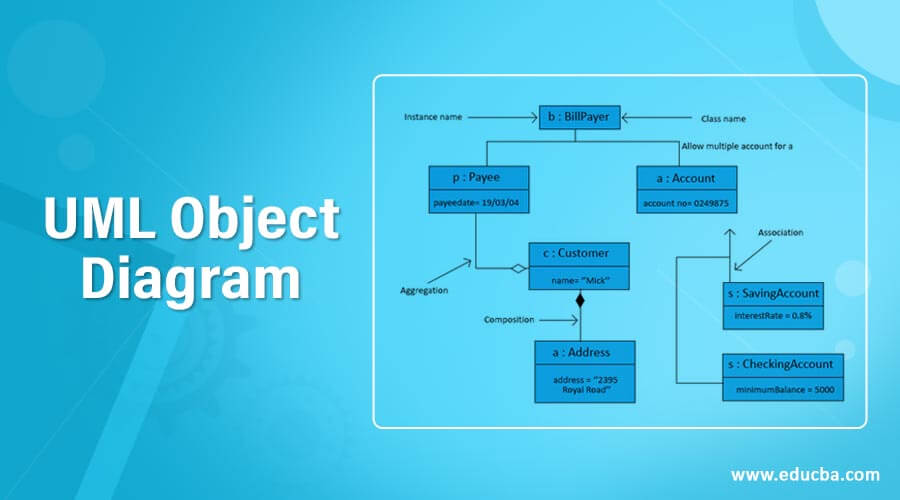
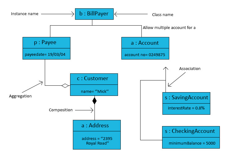
For example, let see the object diagram below:
An object diagram can be viewed as a unique case of the class diagram. Object diagrams will make use of a subset with the aspects of a class diagram to be able to highlight the relationship between instances of classes in the future. They can be useful in realizing class diagrams. They do not display anything architecturally different than class diagrams but reveal multiplicity as well as functions.
- The object diagram describes the behavioral relationships among class instances during a point in time.
- This captures dynamic as well as runtime modifications in our condition of the program.
- It could consist of data values of entities or attributes inside the structure.
- An object diagram displays how those objects act at run time.
While objects will be instances of classes, an object diagram is an overview of the objects in a program during a particular moment in time, such as the relations together. You need to use object diagrams whenever it can be required to model or look around the values of attributes and condition of the object at distinct phases throughout the application’s performance. They can be very helpful to model do it yourself performance of a complicated process or computation operation. You can create a review of the first phases of objects along the way and the last phases of objects to find the entire picture. Because it displays instances instead of classes, it is also known as an instance diagram.
Fundamental Object Diagram Symbols and Notations
Given below shows fundamental object diagram symbols and notations:
1. Object Names
Every object is represented, such as a rectangular shape, which provides the name through the object and class underlined along with shared using a colon.
2. Object Attributes
Just like classes, it is possible to list object attributes within an individual box. Even so, as opposed to classes, object attributes must have values allocated to them.
3. Links
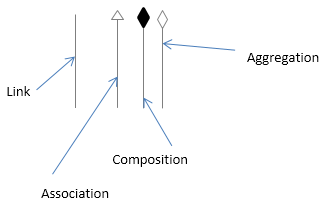
Links often instances connected with relationships. You are able to draw the link when using the lines applied to class diagrams.
- Link: We use a link to symbolize a relationship between two objects.
- Extension or Association: Association is a reference relationship among two objects (or classes).
Association notation in the above diagram
When an object uses another, it can be referred to as an association. We apply association when one object referrals an associate of the other object. The Association could be a single direction or may be bi-directional. We use an arrow to symbolize association.
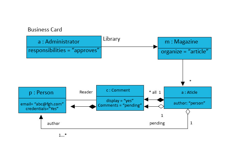
Example: The object of the Administrator class is associated with an object of the Magazine class.
As per the above figure, an object diagram using an association.
- Composition: Composition can be described as a form of relationship where children are not able to occur independently of the difference.
Composition notation in the above diagram.
Here Site is a class containing 0 (zero) or more objects that implement Post. The collection called content. It means one Site using many Post relationships.
So when independent existence with the children is definitely not possible we ideally, use a composition relationship. We use a filled-up diamond within the containing object with a line connecting to that towards the contained object.
- Aggregation: Aggregation signifies a “has a” relationship.
Here hollow diamond with not a solid it is an Aggregation. An Article is an Aggregation of its contents and both the pending and complete set of comments. The hollow diamond, though, doesn’t imply any kind of destruction relationship. If there is a hollow diamond and the Article goes away, the pending comments are not destroyed as well. Now we need that here because the pending comments are also part of the other list, so we don’t want to destroy them twice.
Example of how to make an Object Diagram
As per the above diagram:
- The line between the Magazine and the Article. Messages flow from magazines to articles. That’s the arrowhead. For every one Magazine, there are many articles. The * (star) means 0 (zero) or more. The filled-in diamond represents a composition relationship, which is containment or a contains relationship. In the code, one object would actually contain another object, not a reference to an object but the object itself. In other words, the Magazine contains articles.
- It contains should be destroyed as well. A Magazine has a dictionary, it contains a dictionary of articles indexed by the author, and an author is a person object. In other words, this is effectively a hash table. UML call, this is a qualified association. So in every qualified association: a key (attribute) and value. The object indexed by a key, and the object itself is the associated value.
Example:
Code:
class Magazine {
private static instance = new Library();
public static instance() { return instance;  }
private HashMap<Person, Article> articles;
public void displayPendingComments()……
public void iAmApproved (Comment pending)…..
In the object diagram, list the responsibilities, not individual methods.
Conclusion
UML object diagrams are helpful once building organization data. By simply effectively building attributes as well as associations of class entities, we could map these types of class diagram features to entity beans with an instance. Object attributes map to abstract discover techniques for persistent fields and relating tasks map to abstract gain access to options for relationship fields. Navigability decides if relationship access methods come in equally related entity beans or simply an individual. Practically, multiplicity notation decides the right category for related fields, life cycle problems, and flowing delete features. Therefore an object diagram is an overview of the structure as well as data it can be managed (just how it must be managed).
Recommended Articles
This is a guide to UML Object Diagram. Here we discuss the introduction, fundamental object diagram symbols, and notations and example. You can also go through our other suggested articles to learn more –


