Updated April 4, 2023
Introduction to XOR gate
The XOR gate is defined as a type of logical gate that also has other names as EXOR or EOR. It gives the true output when the true inputs number is odd and gives a false value when the true input number is not odd. It is basically used for representing the inequality function that means if inputs are not the same, the output is true; otherwise, false. For the XOR gate, there is no direct Boolean expression like AND or OR gate have.
How does the XOR gate Works?
The bitwise methods are sued for evaluating the binary representation for any two input values. In the binary representation, for every bit, the EXOR operation is performed to get the result. In the EXOR operation, when one of the bit is true and the other bit is false, the output is always true, and if both the input bit is true or both input bits are false, the output is always false, and the output, in this case, is always 0. And when one input value or both input value is NoData, the output is also NoData.
In the XOR gate operation, the exclusive disjunction operation is performed. When the XOR gate has more than 2 inputs, then the circuit behavior directly depends on its execution. The primary condition for it is to an odd number of high inputs so that result is always high and equal to one.
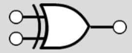
In the below diagram, the symbolic representation of the XOR gate is described. This symbol is defined in IEEE format and is the standard symbol for the XOR gate.
Example:
Input 1 = 5 and its binary representation is 00000101
Input 2 = 3 and its binary representation is 00000011
Bitwise XOR
Output = 6, and its binary representation is 00000110
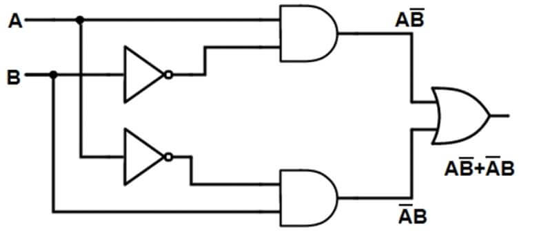
In the below diagram, the circuit diagram of the XOR gate is described. In this diagram, we have two inputs A and B. The circuit contains two NOT gates, two AND gates and one OR gate. The output received from the circuit is the same as the XOR gate.
Truth Table of XOR gate
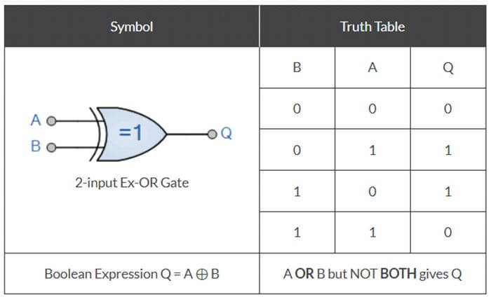
In the below diagram, the truth table for the two input XOR gate is attached.
The Boolean expression for the above table is Q = A ⊕ B.
In the above table, we have two input gate named as gate A and gate B, and from that, we have four cases that are mentioned in the above table:
- Case 1: When both inputs are low, that means 0. According to it, when both the inputs are the same, the output is always turned to low (0). So when A and B is 0, then the output Q will also be 0.
- Case 2: When one input is high and one input is low, the output from the XOR gate is always high. In this case, we have B =0 and A = 1, so the output Q =1.
- Case 3: When one input is high and one input is low, the output from is always high. In this case, we have B =1 and A = 0, so the output Q =1.
- Case 4: When both inputs are low, that means 0. According to it, when both the inputs are the same, the output is always turned to low (0). So when A and B is 1, then the output Q will also be 0.
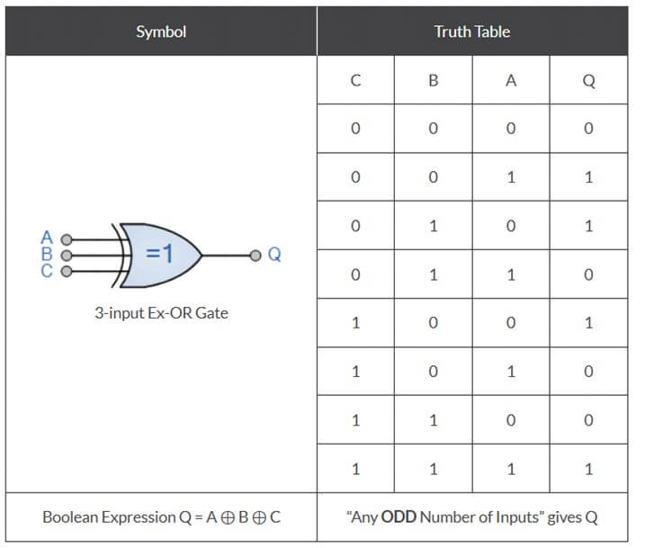
In the below diagram, the truth table for the three input XOR gate is attached.
The Boolean expression for the above table is Q = A ⊕ B ⊕ C.
In the above table, whenever we have the odd number of the high bit as input, the output is always 1. And whenever we have an even number of high input bit (1), the output is always set to 0. In cases 1, 4, 6 and 7, when the input is equal to 1 is in an even number, the output received is 0 always. And in case 2, 3, 5, 8, when input bits equal to 1 is in an odd number, the output received from the XOR gate is always.
Uses of XOR gate
Different uses are mentioned below:
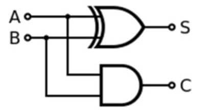
1. Used for Addition
It can be used for an additional purpose. The single-bit adder can be easily design using the XOR gate. The single-bit adder will add two bits and will generate a single bit result.
S is output, and C is carried bit.
For Example:
If we have two bits, 1 and 1, and we do binary addition, the result will 10, and in decimal, we get result 2. The main focus of the half adder is to get the output from the XOR gate, and the carry bit is getting from AND gate. These single bit adder can be combined to form an n-bit adder and can be used further for long binary numbers.
2. Pseudo-random Number Generation
It can be arranged in such a manner so that they form a linear feedback type shift register. The linear shift register is also known as a Pseudo-random number generator.
3. Sequence Detection and Correlation
It has the functionality to produce the low output (0) when both the inputs are high are both the inputs are low. When we have a long data sequence, and we have a requirement to search any particular bit sequence, It can be used for finding the data bit sequence. The accuracy can also be determined by calculating the 0 counts in the target sequence. It is used for correlation as they are attached in the decoder to extract parity from it.
Conclusion
It is a digital circuit used for bitwise operations in an electrical circuit. When a number of input bit equal to 1 is in an odd number in the XOR gate, the output is always 1, and when the number is in an even number, the output is always 0. The XOR gate is used for pseudo-random number generation, used for designing single bit adder and many more.
Recommended Articles
This is a guide to XOR gate. Here we discuss the introduction; how does XOR gate work? Truth table and uses, respectively. You may also have a look at the following articles to learn more –

